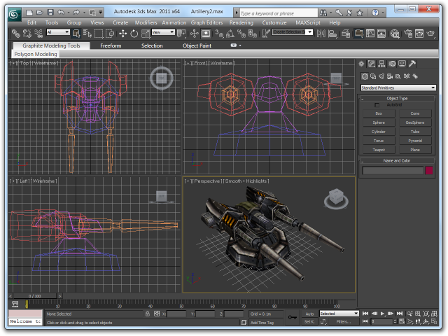

Press the Esc button to exit the command. Step 3: We can set this data from the keyboard entry option and click on the keyboard entry to set the data. Step 2: By using the Upward and Downward arrow key, which is present in the parameter box area. Here you can set the length, width, height of the box according to you by type date from the keyboard. Instead, go to the parameter option of that shape. For setting parameters during the drawing of the shape, follow the same step as taught before for drawing an object and now don’t exit from the command. Step 1: We can set the parameter of the drawn shape at any time during or after drawing the 3D models of shape. And drag the mouse cursor to give the length and width of the box. I will take my cursor on the top viewport click anywhere in the grid area or out of the gird area. Step 9: Now, I will show you by doing all these steps in one of the other viewports. Step 8: We can see any viewport on the Fullscreen by pressing Alt + W from the keyboard. Step 7: Deleting an object, selecting it by clicking on it, and pressing the delete button from the keyboard. Step 6: We can see the box all view from any viewpoint at any time. Step 5: For exiting for box command, press the right key. Step 4: Or Downward Direction for giving Depth and click to leave.

Step 3: Again, drag the cursor in an Upward direction to give the Height of the box. Now drag the cursor by holding the mouse button for giving the Length and Width of the box and click. Next, click anywhere on the Grid area or out of the Grid area. I will take my cursor in Perspective view. Top view, Front view, Left view and Perspective view. Step 2: Move your cursor on any viewport, i.e. Step 1: Click on the Box shape from Standard Primitives. Then, go on the Standard Primitives option and choose the shape from here. We can also create these shapes from Create option, which is present on the top ribbon. Step 4: We have many shapes here, such as Box, Sphere, Cone, etc.Īlmost all shape has some steps for drawing it, and their Parameter setting is also same. We will learn from ‘Standard Primitives’.Select the “Standard Primitives” option. Step 3: We have different options for 3D Modeling Objects here.

Methods to Use “Create” Option in 3D Models.īelow are the methods explained to use the “Create” option: Method #1 We will use the ‘Create’ option for creating the 3D models. We have many options in the common panel, such as Create, Modify, etc. We have here Common Panel in our work area at the right corner. Let’s start by learning 3D Max Models in a step by step manner. Here I will tell you a few simple steps by which you can easily get knowledge about 3D Max Models. We generally take its unit in Inches because when we import any other model in or project, there will be no change in the imported model’s unit. If necessary, apply an STL Check modifier to the selected geometry and run it to check for improper vertex or polygon settings that would prevent the geometry from printing properly.Step 6: We have a system unit step option here.Then, apply a Smooth modifier and Unify Normals modifier if necessary and adjust their settings to finish cleaning up the geometry.After the model finishes importing, go to the Command Panel > Modify, select the model, then apply the Edit Mesh modifier and weld vertices manually.If the Import times are unacceptable, it may be preferable to quit 3ds Max, re-import the file, but uncheck the Weld Vertices, Auto-Smooth and Unify Normals boxes. Note: Depending on the complexity of the file, the Vertex Weld operations and Auto-Smooth options (especially on high-resolution landscape models) may take a considerable amount of time when importing the model.When the Import STL File dialog appears, click on OK.


 0 kommentar(er)
